FAQ
- What is Vesuvius Challenge?
- What dates do I need to know?
- What's the historical background of Herculaneum and the scrolls?
- Where can I read the texts Vesuvius Challenge has uncovered?
- What about other texts from the physically opened Herculaneum scrolls?
- Where can I find more background on this effort?
- What if I would like to contribute, but don’t have time to compete for the Grand Prize?
- Can I share my progress on social media?
- I’m outside the United States, can I participate and win prizes?
- Do I have to pay taxes on my prize earnings?
- I’m a researcher or student. Can I publish my results?
- I have some ideas but need help. Who can I ask?
- I have made some progress, who do I inform about this?
- Do we really need 7.91µm or 3.24µm resolution? These data files are huge!
- Can machine learning models hallucinate letters that aren't there?
- What is papyrus and how is it made?
- How big are the letters, and where can we expect to find text?
- How can we get more ground truth data? Can I make my own carbonized scrolls?
- What software is available currently that might help me?
- Where can I find collaborators?
- What would the papyrus scrolls look like when unrolled?
- Why are there no spaces in the text?
- How does CT-scanning work exactly?
- How does CT reconstruction work?
- How should the intensity values in the CT scans be interpreted?
- What signals might be present in the 3D X-ray scans for ink detection?
- Does segmenting and flattening need to happen before ink detection?
- Fiji/ImageJ crashes, what can I do about that?
- How are the scroll slices oriented?
- What happened to the people when Mount Vesuvius erupted? 😢
- Why did you decide to start this project?
- I have a lot of money! Can I help sponsor this?
- I’m a journalist and I would like to interview someone from Vesuvius Challenge!
- Do you have a scroll that looks like the Nintendo logo from GoldenEye N64?
- Do you have a super-cringe, over-the-top, and factually questionable trailer video for the competition?
What is Vesuvius Challenge?
Vesuvius Challenge is a machine learning, computer vision, and geometry competition to read the Herculaneum scrolls. The scrolls were buried and carbonized by the eruption of Mount Vesuvius in 79 AD. After their discovery in the 1750s, some were opened physically, mostly destroying them but revealing some Greek philosophy and Latin works.
A few hundred scrolls were excavated that were never opened, and remain rolled up with their contents sealed away. Our community is building methods to read these scrolls using micro-CT and an algorithmic pipeline using machine learning and computer vision.
We've awarded over $1,000,000 in prizes and broken through, revealing complete passages of Greek philosophy from the inside of a closed Herculaneum scroll for the first time. Now we are continuing - we want to go from reading 5% of one scroll to reading multiple complete scrolls. Join us to win prizes and be a part of history!
What dates do I need to know?
The 2024 prize deadlines closed on December 31, 2024, and we are now evaluating the submissions and preparing the next stages. Join the community to stay tuned!
What's the historical background of Herculaneum and the scrolls?
We have a background page for that!
Where can I read the texts Vesuvius Challenge has uncovered?
Check out these images of some text we've so far revealed!
Here are the scholarly publications so far resulting from Vesuvius Challenge:
- Revealing Text from a Still-rolled Herculaneum Papyrus Scroll (PHerc. Paris. 4) (2023 First Letters results)
- The final columns of PHerc.Paris. 4 revealed through virtual unwrapping (2023 Grand Prize results)
Also of interest:
What about other texts from the physically opened Herculaneum scrolls?
Most are by Philodemus. This is a list of English translations we have found so far:
- Philodemus: On Anger. (2020), David Armstrong & Michael McOsker. SBL. ISBN 1628372699
- Philodemus: On Death. (2009), W. Benjamin Henry. SBL. ISBN 1-58983-446-1
- Philodemus: On Frank Criticism. (1998), David Konstan, Diskin Clay, Clarence, E. Glad. SBL. ISBN 1-58983-292-2
- Philodemus, On Piety, Part 1. (1996). Critical Text with Commentary by Dirk Obbink. Oxford University Press. ISBN 0-19-815008-3
- Philodemus, On Poems, Book 1. (2001). Edited with Introduction, Translation, and Commentary by Richard Janko. Oxford University Press. ISBN 0-19-815041-5
- Philodemus, On Poems, Book 2, with the fragments of Heracleodorus and Pausimachus. (2020). Edited with Introduction, Translation, and Commentary by Richard Janko. Oxford University Press. ISBN 9780198835080
- Philodemus, On Poems, Books 3-4, with the Fragments of Aristotle, On Poets. (2010). Edited with Introduction, Translation, and Commentary by Richard Janko. Oxford University Press. ISBN 0-19-957207-0
- Philodemus, On Property Management. (2013), Voula Tsouna. SBL. ISBN 1-58983-667-7
- Philodemus, On Rhetoric Books 1 and 2: Translation and Exegetical Essays. (2005). Clive Chandler (editor). Routledge. ISBN 0-415-97611-1
- David Sider, (1997), The Epigrams of Philodemos. Introduction, Text, and Commentary. Oxford University Press. ISBN 0-19-509982-6
- Philodemus: On Methods of Inference. 2nd edition. (1978). Phillip Howard De Lacy, Estelle Allen De Lacy. Bibliopolis.
Where can I find more background on this effort?
Academic papers
- Data papers:
- Hard-Hearted Scrolls: A Noninvasive Method for Reading the Herculaneum Papyri (Stephen Parsons’ PhD dissertation)
- From invisibility to readability: Recovering the ink of Herculaneum
- From damage to discovery via virtual unwrapping: Reading the scroll from En-Gedi
- Reading the Invisible Library: A Retrospective (history preprint)
For a comprehensive overview of the field, see this list by EduceLab.
Talks
- Reading the Herculaneum Papyri: Yesterday, Today, and Tomorrow
- Digital Restoration Initiative: Reading the Invisible Library
- Reading the Invisible Library: Virtual Unwrapping and the Scroll from En-Gedi
- 2023 symposium
Books
The best book we have found is David Sider’s The Library of the Villa dei Papiri at Herculaneum.
Here are some other excellent books we recommend:
- Herculaneum: Italy's Buried Treasure, Joseph Jay Deiss
- Buried by Vesuvius: The Villa dei Papiri at Herculaneum, Kenneth Lapatin (ed.)
- Rediscovering Antiquity: Karl Weber and the Excavation of Herculaneum, Pompeii, and Stabiae, Christopher Charles Parslow
- Scribes and Scholars: A Guide to the Transmission of Greek and Latin Literature, Leighton D. Reynolds & Nigel Guy Wilson
- 24 Hours in Ancient Rome, Philip Matyszak
- Die Papyri Herkulaneums im Digitalen Zeitalter, Kilian Fleischer
- Contains an estimate of how much text we hope to find when we read the scrolls, which we translated into English.
- Opera incerta sugli Dèi, Marzia D’Angelo
Videos
- Secrets of the Villa of the Papyri
- History of Pompeii: Villa of the Papyri
- Reading the Papyrus Scrolls found at Herculaneum
- Out of the Ashes: Recovering the Lost Library of Herculaneum
- For more videos see this page
Previous media coverage
- Watch this interview with Dr. Brent Seales on 60 Minutes!
- The UnXplained
- Great article by Smithsonian Magazine
- More articles and videos on this page
What if I would like to contribute, but don’t have time to compete for the Grand Prize?
- Join our Discord to learn about current efforts and how you can pitch in.
- You can make smaller open source contributions, which would benefit the whole community. Everyone in the community will be grateful for your work, and you might even be able to win a prize - see those already awarded!
Can I share my progress on social media?
Yes, in fact we encourage you to share your progress. Be sure to also post in our Discord, to get feedback from the community.
The only exception is that per the data agreement, you’re not allowed to publicly share material revelation of text (e.g. entire words) without our permission (including the associated code), or share the raw data. You are allowed to share these things on Discord, since everything uploaded on Discord falls under the same data agreement as our data server.
I’m outside the United States, can I participate and win prizes?
Absolutely! As long as we can legally pay you (no US sanctions) you can win prizes.
Do I have to pay taxes on my prize earnings?
This depends on the jurisdiction you live in, but generally yes, you do have to pay taxes. Consult your tax advisor.
I’m a researcher or student. Can I publish my results?
- Any publications and presentations must cite the EduceLab-Scrolls Dataset.
- You won’t publish any revelation of hidden text (or associated code) without the written approval of Vesuvius Challenge.
We very much encourage researchers and students to work on this! Be sure to reach out to us on Discord or by email.
I have some ideas but need help. Who can I ask?
Definitely ask the Discord community!
You are also welcome to reach out to our team directly; though as contest organizers we can only provide limited information regarding specific ideas or submissions and will largely point you towards public resources such as this FAQ or the public Discord channels.
I have made some progress, who do I inform about this?
Please email us at team@scrollprize.org. We will keep it confidential. We appreciate you keeping us in the loop!
If you're open to sharing your improvements publicly (and be eligible for progress prizes), you can post in Discord.
Do we really need 7.91µm or 3.24µm resolution? These data files are huge!
We don't know yet what the minimum resolution necessary to detect ink is, but this paper suggests that it may be 7.91µm: From invisibility to readability: Recovering the ink of Herculaneum.
Can machine learning models hallucinate letters that aren't there?
This is a risk for models that are trained on letterforms. We strongly recommend that participants guard against the risk of hallucination in their models, and will review all submissions with this in mind.
What is papyrus and how is it made?
Papyrus is a grassy reed that grows along the banks of the Nile in Egypt. It can grow up to 4.5 meters tall and 7.5cm thick. The tough outer rind is peeled away. The green inner pith is peeled or sliced into strips.
The strips are laid out in two layers in a grid pattern. They are pressed together until the layers merge like velcro. And then left out in the sun to dry, where they turn light brown. The sheets – called kollemata – are smoothed out with an ivory or seashell ruler. The kollemata are then glued together with paste made of flour and water. Then the areas where they are joined are hammered smooth. This forms a long piece of papyrus, usually 15-30 feet, comprised of up to 20 kollemata.
The Papyrus is rolled up around a dowel called an umbilicus. Portions of it are unrolled for writing. The first section, called the protokollon, is usually left blank. Text is written in columns with a quill and inkwell. Inks are made of varied substances.
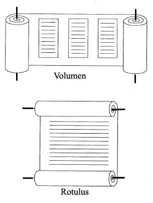
There are two ways you can write on papyrus: horizontally (“volumen”) or vertically (“rotulus”). All of the Herculaneum papyri are horizontal scrolls.
- Nat’s post
- Meet Some Of The Last Papyrus Makers In Egypt Keeping A 5,000-Year-Old Craft Alive
- Myriam Krutzsch papyrus workshop
How big are the letters, and where can we expect to find text?
Letter sizes vary, and of course we don’t know what’s inside the unopened scrolls, but we expect the opened fragments to be fairly representative. You can measure how big the letters are by looking at the aligned surface images, which have a voxel resolution of approximately 3.24µm, like the original CT data (though there can be some local variation due to the registration / flattening process). So you could open, for example, fragments/Frag1.volpkg/working/54keV_exposed_surface/ir.png, measure a letter size in pixels, and multiply by 3.24µm.
There are also some measurements in this paper by Richard Janko, though it’s a little hard to infer actual letter sizing from it. If someone wants to do a more thorough review of the range of letter sizes found in all the Herculaneum papyri, we’d happily include your results here!
From our first Q&A with the Papyrology Team, we learned (summary courtesy of Santiago Pelufo on Discord):
- 2 orthogonal layers of fibers in a sheet.
- ~100um sheet thickness
- Scroll outer layer of a sheet = back of a sheet = vertical fibers.
- Scroll inner layer of a sheet = front of a sheet with writing = horizontal fibers (text written here).
- Sheet layers unlikely to delaminate with carbonization
- Carbonization likely fuses multiple sheets (big issue IMO)
- 10-20cm blank at start and end of scroll.
- 4.5-6cm columns, 1/6 of column space between columns
- ~1/8 height paddings top and bottom
- Text typically written on the inside (to protect against damage), and on the side with horizontal fibers (easier to write on).
How can we get more ground truth data? Can I make my own carbonized scrolls?
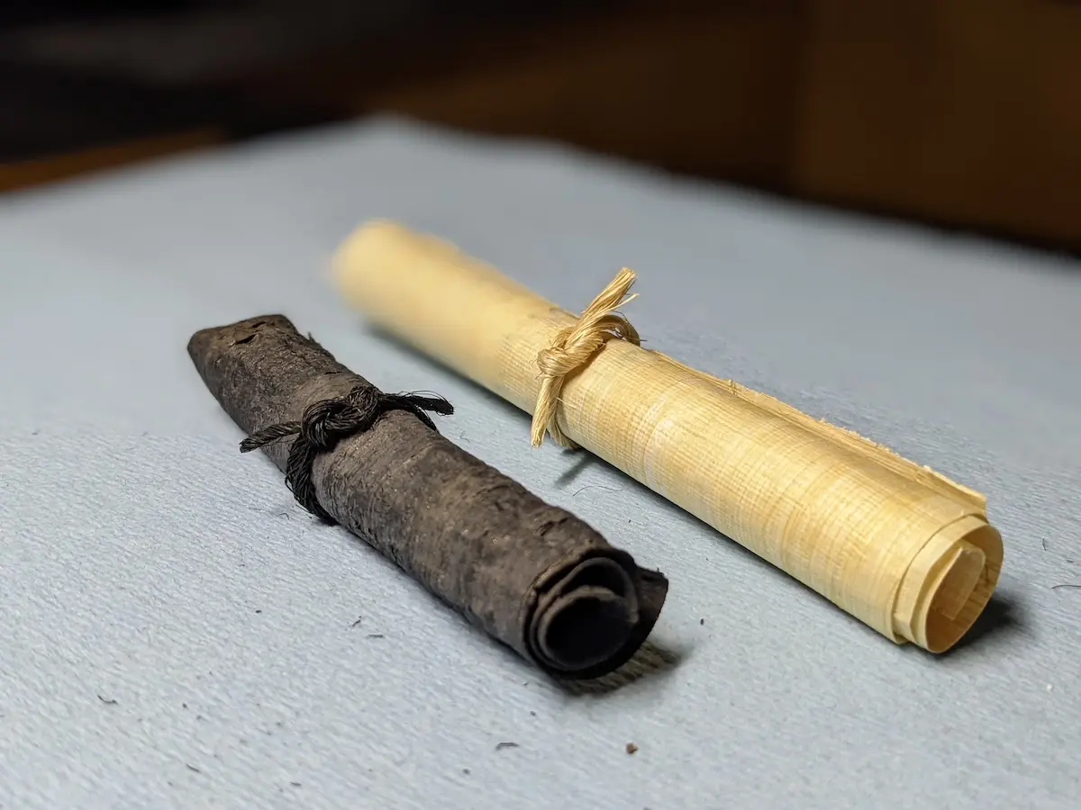
Yes! Just buy this papyrus on Amazon, roll it up, and put it inside a Dutch oven at 500F+ (260C+) for a few hours.
This is very instructive and we highly recommend doing it! You will see how fragile the charred scroll is, how it blisters in the heat, how the layers can separate, how it turns to dust as you handle it.
Of course, for it to be useful as ground truth data, you will need to find someone to let you image it in their CT scanner.
What software is available currently that might help me?
The two main pieces of software developed by Dr. Seales’ lab are Volume Cartographer and ink-id. Both are open source and available on Github.
In the tutorials we also show you how to use generic software to work with 3D volumes (Fiji) and meshes (MeshLab).
There is a growing body of open source software now available as a result of Vesuvius Challenge. To learn more, check out the previous prizes that have been awarded to many of these efforts and our list of community projects.
Where can I find collaborators?
In this Discord thread.
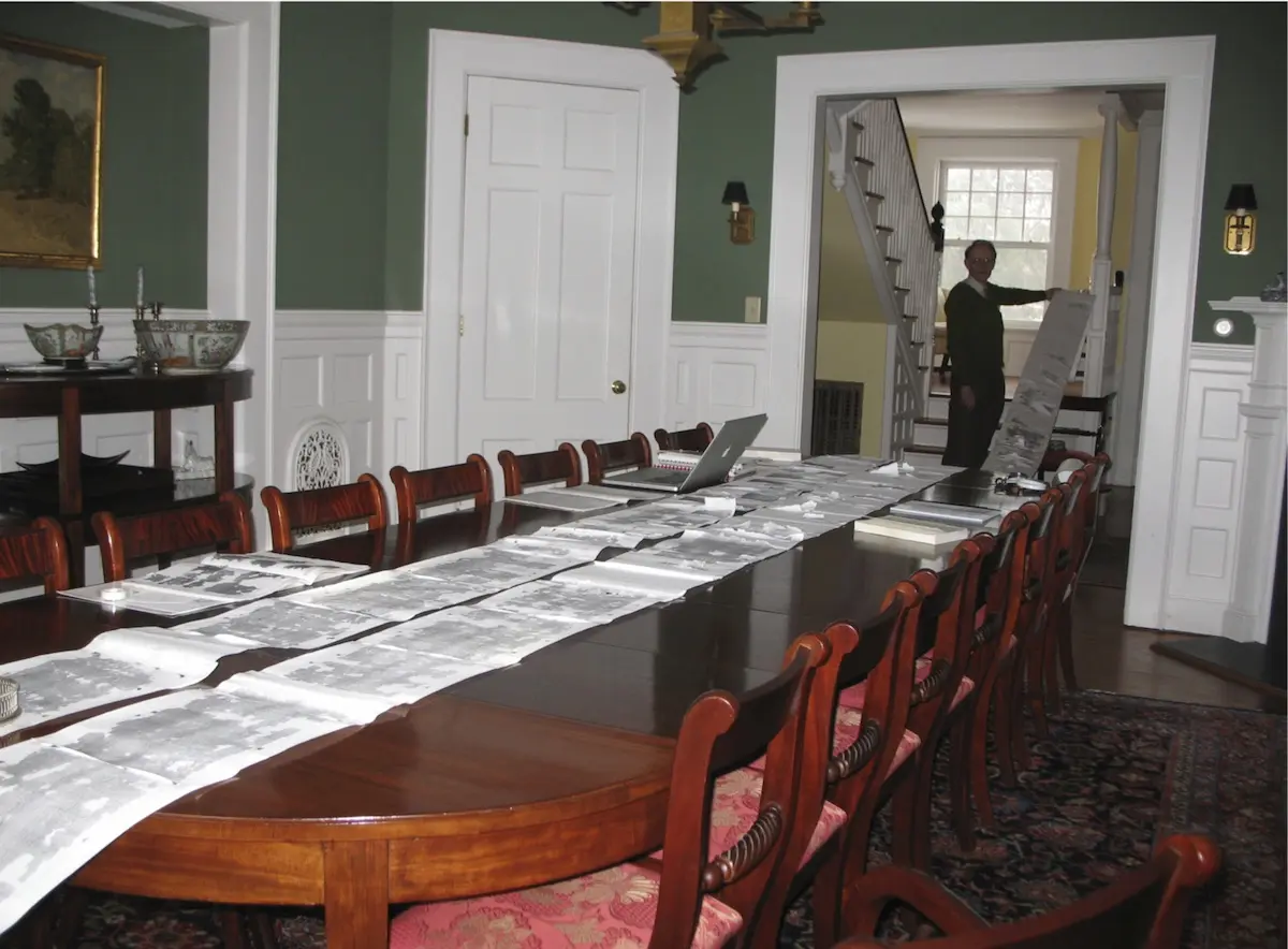
What would the papyrus scrolls look like when unrolled?
Something like this:
Why are there no spaces in the text?
In ancient Latin and Greek, they didn’t use spaces! Spaces were added later to aid foreign language learners.
How does CT-scanning work exactly?
We take X-ray photographs of the object from different angles. Typically this is done by having an X-ray source on one side of the object, and an X-ray camera on the other side, and rotating the object on a platform. If the object doesn’t fully fit in the frame of the camera, it can be moved around as well.
- Resolution: the dimensions of each pixel in an X-ray photo, typically denoted in µm (micrometers or “microns”). Lower is better. We scanned the scrolls at 7.91µm, which we think should be enough to detect ink patterns, but we scanned the fragments at 3.24µm just in case. Renting beam time on a particle accelerator is expensive, but if we need to we can go back and scan objects at even lower resolutions.
- Energy level: the energy of the X-ray electrons, typically expressed in keV (kilo electronvolts). For particle accelerators this is one precise number, whereas for bench top scanners this is more of a range. We think lower is better, since carbon responds better to lower energy levels. We scanned everything twice, at 54keV and 88keV (though for the scrolls we only had time for a smaller slice at 88keV).
At high resolutions the field of view of the camera is too small to capture the object in its entirety, so multiple passes have to be made. Typically these are stitched together as part of the scanning process.
From the X-ray photos from different angles we can reconstruct a 3D volume, using a clever algorithm called tomographic reconstruction (which is where “CT scanner” gets its name; ”computed tomography”). This is typically done by software that comes with the scanner.
The resulting 3D volume is like a 3D image. Each unit is called a “voxel” (instead of “pixel”), and has a particular brightness (it’s greyscale). This 3D volume is typically represented as a “.tif image stack”. This is just a bunch of .tif images where each image (called a “slice”) represents a different layer the z-direction, typically starting at the bottom and moving upwards.
How does CT reconstruction work?
Tomographic reconstruction is used to convert the initial X-ray projection images into the cross-sections we are used to seeing from computed tomography (CT). In our case, filtered backprojection is used as the reconstruction algorithm. In the case of scrolls scanned in the parallel beam of a synchrotron, we also use a "grid scan" technique to tile high resolution projections together and scan objects larger than the sensor field of view.
For more information about the reconstruction method, check out:
- Appendix A.1 of "EduceLab-Scrolls: Verifiable Recovery of Text from Herculaneum Papyri using X-ray CT"
- "Data processing methods and data acquisition for samples larger than the field of view in parallel-beam tomography"
- The algotom reconstruction package
Reconstruction methods are out of scope for Vesuvius Challenge, which focuses on processing the reconstructed images. That said, if you have specific ideas you would like to share with us, please do so by reaching out to team@scrollprize.org!
How should the intensity values in the CT scans be interpreted?
The intensity values should be considered relative: within a CT scan, a higher value indicates higher radiodensity compared to a lower value from the same scan. There are not units attached to these values that have an absolute physical interpretation, or that allow direct density comparisons between scans. These forms of data are sometimes called qualitative (for relative values) and quantitative (for absolute values with units), even though they're both "quantitative" in the sense we often think of, in that they are numerical.
Relative values like this are typical in CT due to the nature of the imaging technique. The medical CT community has a convention called the Hounsfield unit (HU) that approaches quantitative data, but has caveats. The HU is calculated based on a linear ramp using baseline attenuation measured from distilled water (defined as zero HU) and air (-1000 HU). Certain tissues then tend to occupy particular ranges, for instance bone can commonly reach 1000 HU. This can be helpful in the right application, but the HU is still considered unreliable as an absolute value, particularly between different scans.
Seth Parker described this with respect to our data using an analogy to photography:
Filtered back projection doesn't set a mean explicitly- every voxel is calculated as the weighted sum of projections of that voxel, with the weights derived analytically. So in general the intensity scale is all relative. A loose analogy here is determining the element of an object by taking its color photograph: color in the image is a function of the object's chemistry, but also the color of the incident light, ambient light bouncing around the scene, the exposure properties of the camera, the light response of the sensor/film, etc. Not only that, but multiple materials may have the same color under a specific lighting condition. If you don't have some way of disentangling those effects (for example, controlling lighting, capturing under multiple exposure conditions, having known samples in the FOV to use for calibration), then it's hard to say much beyond what the color is.
The ensuing discussion is also informative and can be found on our Discord.
Based on this, the raw reconstruction values for a scan do not have units or physical interpretations attached to them. These 32-bit float values are typically in the range [-0.1, 0.1] or smaller. For more recent scans, we are releasing .hdf files that contain these original reconstruction output float values, so you can experiment with your own intensity windowing. For the 16-bit integer .tif slices that we release, we map the float range to [0, 2^16-1] by choosing a minimum and maximum in the raw float range and scaling accordingly. The fragments and all more recent scans use the 0.01 percentile and 99.99 percentile as the window min and max. Scroll 1 and Scroll 2 use 0.1 and 99.9, to achieve visually comparable output since they have so much more papyrus in the field of view.
Reconstruction outputs should be nonnegative by the principles of backprojection (there can't be negative X-ray attenuation). But noise and other processes lead to some negative values in the reconstructions. This is typical with CT. To remove these negative values, the window min could just be clamped at zero. This would result in an image where air would be black, and there would be more visual contrast.
We did not clamp the minimum at zero, instead using percentiles. Air therefore does not appear black in the .tif slices, but is gray and has some noise. For ink detection, we are looking for something subtle, and are training models to detect it. Removing all negative values from the reconstructed image makes the output visually resemble expectations, but is inherently destructive. We don't yet know if there might be any subtle ink signal in the "noise" of the negative values, and so leave the data as unaltered as possible so the models can decide for themselves what to look for.
If you want to experiment with comparing scans across energies, there are some materials of known composition in the field of view that are consistent between scans, and you may wish to use them as a sort of baseline. For example, air is present in all scans, and the scroll cases are made of Nylon 12.
What signals might be present in the 3D X-ray scans for ink detection?
There remain open questions, but we do know the ink is sometimes directly visible as a "crackle" pattern, a texture resembling cracked mud that appears where the ink sits proud of the surface and appears to have dried.
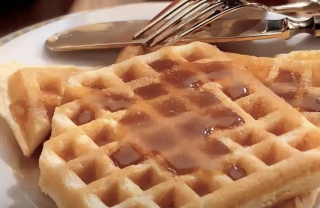
There may be other patterns present that are detectible by machine learning. We suspect that ink might be filling in between the grid pattern of papyrus, kind of like syrup filling in gaps in a waffle.
Ink might also be sitting on top of the papyrus, causing a slight bump on the surface. In Tutorial 5 we show several examples of where the ink is directly visible in slices of 3D X-ray scans, which is promising. The talks at the top of this page also go into some details.
There might be some effect of indentation of the writing instrument, but it’s probably not very significant. The thought has generally been that any indentation effect would be even smaller than ink w.r.t. the scan resolution and maybe not significant when compared against the natural relief of the papyrus fibers. However, this has not been explored in detail on this type of material (look at the paper "Revisiting the Jerash Silver Scroll" for work on an etched metal scroll), so we don’t know for sure.
It could be worthwhile to try to reverse engineer what machine learning models are seeing, so that perhaps we can see it more directly. Perhaps this could influence other ink detection methods or future scanning efforts.
Does segmenting and flattening need to happen before ink detection?
This ordering is largely historical and due to the way we�’ve constructed label sets, which relies on doing the segmentation and flattening first. But this can’t be the only way to do it, and we’d love to see the pipeline get shaken up.
For example, the model input of ink detection could be sampled directly from the original 3D X-ray volume, instead of using a “surface volume” as an intermediate step. This could avoid loss of resolution during the sampling process into a differently oriented volume, which happens when constructing a surface volume.
The downside of such an approach is that a lot more data needs to be accessible on disk, since the original 3D X-ray volumes are much bigger than the surface volumes (37GB vs 1.6TB in total for all fragments). This can be problematic for cloud training, which might not have enough available hard drive space. However, since we only need to access the voxels around the mesh, the data size could be reduced (creating something like a surface volume, but retaining the original coordinate space, and avoiding any resampling).
Fiji/ImageJ crashes, what can I do about that?
Fiji/ImageJ doesn’t work well with extremely large datasets such as our scrolls or fragment volumes, though downsampling might help. If you’re experiencing problems even with the campfire.zip dataset, then try to increase the memory limit: “Edit > Options > Memory and Threads”. It might also help to run the software in a different operating system, such as in a Linux VM. For example, on Windows the following setup seems to work well: WSL2, Ubuntu 20, Windows 11, using the default WSL X server setup.
A great contribution to the community would be to build an open source 3D volume viewer that is tailored to this problem. If you are interested in building something like that, do let us know in Discord!
How are the scroll slices oriented?
Scroll 1
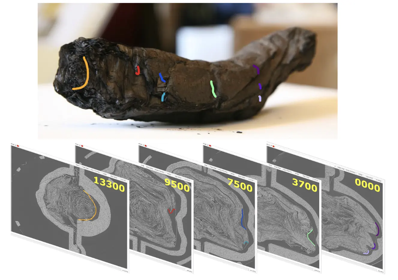
The orientation of Scroll 1 follows the above image. When viewing one of the TIF cross-sections from the scan, the image number increases from the screen toward the viewer’s eye.
Based on the counterclockwise spiral direction in the middle of Scroll 1, the released scans are of the top of the scroll: Slice 0 is in the middle and Slice 14000+ is the top.
Lastly, all of the Herculaneum papyri are known to be "volumen"/horizontal scrolls (see FAQ: https://scrollprize.org/faq#what-is-papyrus-and-how-is-it-made).
Therefore, the direction of a given line of writing should be clockwise around the TIF cross-sections. The bottom of the letters should be on the lower-numbered images, and the top of the letters should be on the higher-numbered images.
Scroll 2
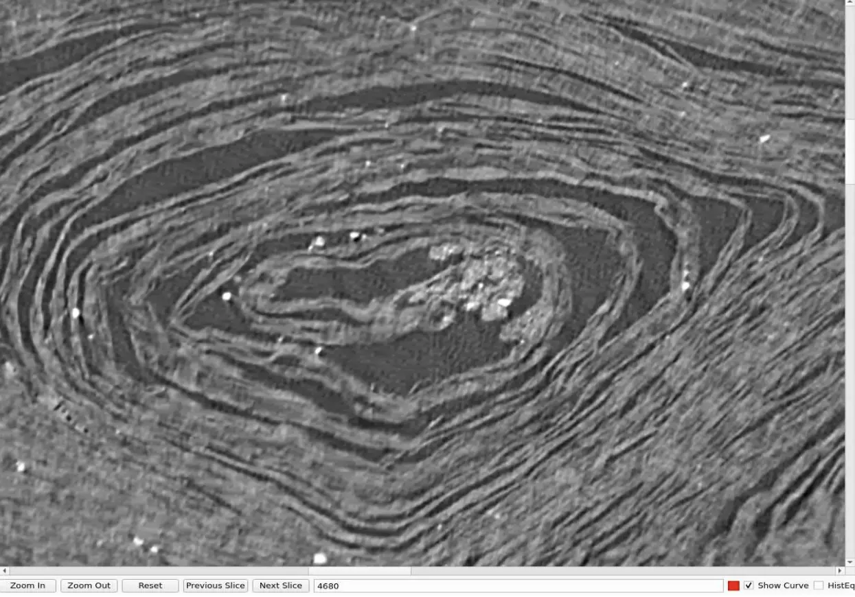
Relatedly, we can likely assume handedness is consistent between the scans of Scroll 1 and Scroll 2 (the TIF cross-section image number increases from the screen toward the viewer’s eye).
There's a region in Scroll 2 where the scroll center appears to have drifted/squished its way outside of the center scanning artifact. Only a few slices are as clear as this example (Slice 4680). The center spiral of Scroll 2 appears to be clockwise, unlike Scroll 1's counterclockwise spiral.
Assuming consistent handedness, a counterclockwise spiral suggests the released half of Scroll 2 is the bottom half of the scroll: Slice 0 is in the middle and Slice 14000+ is the bottom.
The direction of a given line of writing in Scroll 2 would be counterclockwise around the TIF cross-sections, with the bottom of the letters on higher-numbered images and the top of the letters on lower-numbered images.
Scrolls 3, 4, 5
Scrolls 3, 4, and 5 appear to be oriented like Scroll 2, with counterclockwise spirals. However, a change in scanning convention flipped the ordering of the tif stack. When viewing Scroll 3, 4, or 5 TIF cross-sections from the scan, the image number decreases from the screen toward the viewer’s eye. Therefore, the direction of a given line of writing should be counterclockwise around the TIF cross-sections. The bottom of the letters should be on the lower-numbered images, and the top of the letters should be on the higher-numbered images.
Note: This flip in the scanning convention must be accounted for in any rendering pipelines.
What happened to the people when Mount Vesuvius erupted? 😢
We recommend starting with the only surviving eyewitness account: Pliny the Younger, Letters 6.16 and 6.20.
The story of the eruption of Mount Vesuvius has captured imaginations for centuries. The cities of Pompeii and Herculaneum are unique in how well they were preserved. A great introduction to this story is A Timeline of Pompeii.

- Wikipedia
- Books: Recommended reads on Pompeii
- Pompeii, by Mary Beard
- Complete Pompeii, by Joanne Berry
- Life and Death in Pompeii and Herculaneum, by Paul Roberts
- Movies
Why did you decide to start this project?
Nat read 24 Hours in Ancient Rome during the 2020 COVID lockdown. He fell into an internet rabbit hole that ended up with him reaching out to Dr. Seales two years later to see how he could help speed up the reading of the Herculaneum Papyri. They came up with the idea of Vesuvius Challenge. Daniel was intrigued by this idea and decided to co-sponsor it with Nat.
I have a lot of money! Can I help sponsor this?
Vesuvius Challenge Inc. is a 501c3 non-profit organization that was formed solely to solve the puzzle of the Herculaneum Papyri. It is currently funded by the sponsors listed on the homepage, and by many hours of volunteer contributions.
If you want to contribute money to support our operational costs or to increase the prize amounts, please get in touch!
I’m a journalist and I would like to interview someone from Vesuvius Challenge!
Please email press@scrollprize.org.
Do you have a scroll that looks like the Nintendo logo from GoldenEye N64?
Of course (🔊 sound on).